CST諧振腔體設計分析—CST2013設計實例
設置工作平面屬性
建模前需要設置工作平面大小,方便建模。可以選擇 View: Visibility ![]() Working Plane
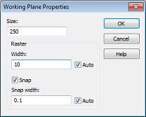
Working Plane ![]() Working Plane Properties 命令,打開工作平面屬性對話框。模型最大尺寸是215毫米,這樣設置一個250毫米大小的工作平面就足夠了。在對話框的Size項輸入250設置工作平面大小,再在Width項輸入10設置柵格大小。設置完成后,相應的設置值也會顯示在用戶界面的狀態欄。
Working Plane Properties 命令,打開工作平面屬性對話框。模型最大尺寸是215毫米,這樣設置一個250毫米大小的工作平面就足夠了。在對話框的Size項輸入250設置工作平面大小,再在Width項輸入10設置柵格大小。設置完成后,相應的設置值也會顯示在用戶界面的狀態欄。
建模操作
After these preparatory steps have been completed, you can now start drawing the figure of rotation. Because the cross section profile is a simple polygon, you do not need to use the curve modeling tools here (please refer to the Workflow and Solver Overview manual for more information on this advanced functionality). For polygonal cross sections, it is more convenient to use the figure of rotation tool, activated by selecting Modeling: Shapes ![]() Extrusions
Extrusions ![]()
![]() Rotate
Rotate ![]() .
.
|
Point |
X |
Y |
|
1 |
0 |
0 |
|
2 |
210 |
0 |
|
3 |
210 |
65 |
|
4 |
129 |
65 |
|
5 |
179 |
139 |
|
6 |
179 |
190 |
|
7 |
148 |
215 |
|
8 |
0 |
215 |
|
9 |
0 |
0 |
After the last point has been entered, the polygon will then be closed. The Rotate Profile dialog box will then automatically appear.
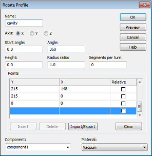
This dialog box allows you to review the coordinate settings in the table. If you encounter any mistakes you can easily change the values by double-clicking on the incorrect coordinates entry field.
The next step is to assign a specific Component and a Material to the shape. In this case, the default settings with component1 and Vacuum are practically appropriate.
Finally, you should assign a proper Name (e.g. cavity) to the shape and press the OK button in order to create the solid.
Smart Pick ![]() and Blend Edge
and Blend Edge ![]()
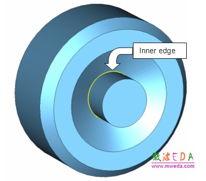
Sharp edges inside cavities are best avoided because strong field singularities will occur at these edges. Therefore, the sharp inner edge (shown on the picture below) should be blended.
The first step towards blending the edge is to pick the edge in the model by entering the smart pick mode via Modeling: Picks ![]() Picks
Picks![]() (shortcut S) in the main view window. Once this mode is active, which is indicated by edges and points in the model being highlighted, you can easily double-click at the inner edge. If the edge is hidden, you can rotate the view using the view changing tools as explained in the Workflow and Solver Overview manual. Sometimes it is also advantageous to switch the drawing mode to wireframe by selecting View: Visibility
(shortcut S) in the main view window. Once this mode is active, which is indicated by edges and points in the model being highlighted, you can easily double-click at the inner edge. If the edge is hidden, you can rotate the view using the view changing tools as explained in the Workflow and Solver Overview manual. Sometimes it is also advantageous to switch the drawing mode to wireframe by selecting View: Visibility ![]() Wire Frame
Wire Frame ![]() , or use the corresponding shortcut Ctrl+w.
, or use the corresponding shortcut Ctrl+w.
Once the proper edge has been selected, the model should look as follows:
If you accidentally picked the wrong edge, you can delete all picks using Modeling: Picks > Clear Picks (shortcut d) and try again.
The next step is to blend the selected edge. Therefore, press Modeling: Tools > Blend . Afterwards, a dialog box will open where you can set the Radius of the blend to 15 mm.
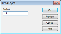
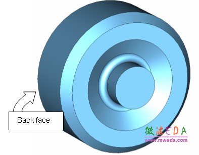
Finally press the OK button to apply the blend. The structure should then look as follows:
-

CST中文視頻教程,資深專家講解,視頻操作演示,從基礎講起,循序漸進,并結合最新工程案例,幫您快速學習掌握CST的設計應用...【詳細介紹】
推薦課程
-
7套中文視頻教程,2本教材,樣樣經典
-
國內最權威、經典的ADS培訓教程套裝
-
最全面的微波射頻仿真設計培訓合集
-
首套Ansoft Designer中文培訓教材
-
矢網,頻譜儀,信號源...,樣樣精通
-
與業界連接緊密的課程,學以致用...
-
業界大牛Les Besser的培訓課程...
-
Allegro,PADS,PCB設計,其實很簡單..
-
Hyperlynx,SIwave,助你解決SI問題
-
現場講授,實時交流,工作學習兩不誤


